


Optimizing an EV Damping Package Using 3D Sound Intensity
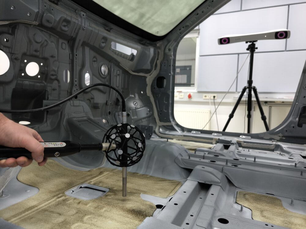
In this case study, Oliver Unruh from Sika Automotive Germany and Martin Gielok from Hyundai Motor Europe Technical Center combine laser scanning vibrometry with Microflown’s 3D sound intensity mapping technology to analyze and optimize damping layouts on a compact electric SUV platform. The study demonstrates how acoustic energy flow visualization enables targeted material redistribution, leading to measurable interior noise reductions while supporting weight and cost efficiency.
Extracted from: Oliver Unruh and Martin Gielok, "HV-Battery Impact on Car Body Acoustics and Damping Package Case Study of the Electric Vehicle", SAE Technical Paper 2025-01-0041, 2025.
STAY UPDATED WITH THE LATEST SOUND AND VIBRATION RESEARCH
Subscribe to our Newsletter
Understanding EV Body Acoustics and Damping Challenges
The vibroacoustic behavior of the body-in-white (BIW) plays a central role in the transmission of structure-borne noise into the vehicle interior. With the introduction of electric powertrains, this behavior is further influenced by the integration of a stiff and heavy high-voltage battery, which alters the dynamic response of key structural components.
To develop efficient damping packages under these conditions, a detailed understanding of vibration and acoustic radiation mechanisms is required. In this study, experimental methods are applied to identify dominant noise-contributing areas and to evaluate how damping materials can be most effectively distributed across the vehicle structure.
Measurement Approach
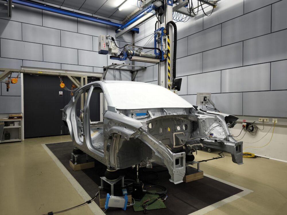
To evaluate the impact of the HV battery and optimize damping layouts, a combination of laser scanning vibrometry and 3D sound intensity mapping is applied.
While vibrometry provides detailed insight into structural vibration, 3D sound intensity mapping directly visualizes acoustic energy flow, including magnitude and direction. This enables fast identification of dominant radiation areas, even on complex geometries or hard-to-access regions.
Together, both methods provide a reliable and efficient basis for targeted damping optimization.
Why Reactive Sound Intensity Matters
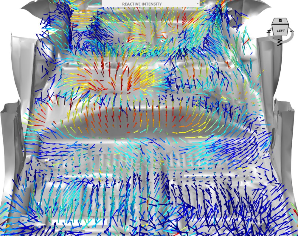
Reactive sound intensity provides unique insight into the non-propagating acoustic energy close to vibrating surfaces, making it highly effective for identifying local vibration behavior and panel interaction.
Unlike sound pressure or active intensity, reactive intensity highlights where energy is stored and exchanged rather than radiated. This makes it particularly suitable for detecting structural hot spots that are critical for damping optimization.
In this study, reactive intensity mapping enabled fast and reliable localization of dominant acoustic regions, even on complex vehicle geometries. The results show strong correlation with vibrometry data, while requiring less measurement effort and providing more intuitive spatial information.
Key Insights: Battery and Damping Interaction
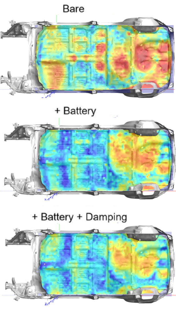
The measurements show that the HV battery significantly alters the vibroacoustic behavior of the vehicle body. Its structural stiffness reduces vibration levels at lower frequencies, particularly in the rear floor area.
At higher frequencies, however, damping treatments become the dominant factor in controlling vibration and acoustic radiation. The results clearly show that battery and damping act in complementary frequency ranges.
Using 3D sound intensity mapping, acoustic hot spots are quickly identified, revealing that critical radiation areas shift away from the floor toward regions such as the wheelhouses, trunk sides, and heel kick panel. This enables a more targeted and efficient distribution of damping material.
Optimized Damping Layout
Based on these insights, the damping layout is redesigned by redistributing material from less effective areas to identified acoustic hot spots. Damping is reduced in rear floor regions and increased in areas such as the wheelhouses, trunk sides, and heel kick panel. This targeted approach improves damping efficiency while supporting weight and cost optimization.
Results and Validation
The optimized damping layouts are validated through vehicle road tests under controlled conditions. The modified package shows clear noise reduction at higher frequencies, while the advanced configuration additionally improves performance in critical low-frequency regions.
Up to 2.5 dB(A) reduction is achieved in the 1400–2000 Hz range, with further improvements around 200 Hz and between 800–1400 Hz. Rear seat passengers benefit in particular, with reductions of up to 3 dB(A).
| Low Frequency Change [dB(A)] | 60 km/h | 80 km/h | 100 km/h | 120 km/h |
|---|---|---|---|---|
| Cabin Average | -0.9 | -0.7 | -0.6 | -1.0 |
| Front Microphones | -1.1 | -1.0 | -0.8 | -1.3 |
| Rear Microphones | -0.9 | -0.7 | -0.5 | -0.9 |
The strong correlation between laboratory measurements and vehicle-level results confirms that 3D sound intensity mapping provides reliable guidance for effective damping optimization.
Conclusion
3D sound intensity mapping enables fast and effective identification of acoustic hot spots, supporting targeted damping optimization in electric vehicles. By directly visualizing acoustic energy flow, the method reduces development time while providing reliable guidance for material distribution. Combined with complementary techniques, it allows engineers to translate laboratory insights into measurable vehicle-level noise reduction.
Full paper available below:
Oliver Unruh and Martin Gielok, "HV-Battery Impact on Car Body Acoustics and Damping Package Case Study of the Electric Vehicle", SAE Technical Paper 2025-01-0041, 2025.
 Scan&Paint 3D
 Robotic Acoustic Scanner